Ingenieurgesellschaft für
technische Software

Car Body Analysis with PERMAS

Finite Element Analysis of car bodies comprise a broad variety of modeling levels from BIW (body-in-white) to trimmed bodies and acoustic models taking into account enclosed and even surrounding air. This variety of structural variants corresponds to different targets from simple stiffness issues up to complex comfort tasks. Therefore, a lot of different methods are applied in car body analysis ranging from linear static analysis up to fluid-structure coupled acoustics.

A typical characteristic of car body models is the use of shell elements. Most frequently, quadrangular linear shell elements are used (together with triangular shell elements). Dependent on the mesh size, up to several million shell elements are used to model car bodies. A car body consists of a larger number of structural parts (typically 50 to 100) which are joined by different techniques like spot welding, bonding, laser welding. In order to generate the meshes of all parts efficiently, incompatible meshing is used for independent meshing.

carbody

Model of a transport vehicle.

Benefits and particular strengths
PERMAS performance aspects
Due to typically large models in body analysis all analysis methods are oriented towards highest possible performance. The following points can be highlighted:
  • comprehensive methods for static and dynamic layout as well as for comfort aspects,
  • fully integrated optimization algorithms designed for very large models,
  • significantly shorter computing times than you expect and know (we accept your challenge: info@intes.de),
  • get lower software costs, lower hardware costs, faster product cycles, more variants, better knowledge of the component behavior and better products through shorter computing times,
  • extremely fast thanks to PERMAS HPC basic technology, such as contact analysis, parallelization and GPU use.
Static Analysis
For computations of static stiffness of a car body, linear static analysis is used. For some load cases like towing or light impact calculations of inertia relief are applied. To check the force flow through any structural member, cutting forces (e.g. through a column or sill) can easily be derived and a summary of the forces and moments is exported (and printed).
Dynamic Analysis
An eigenvalue analysis is performed as a basis for subsequent response analysis. Because cars are not supported on ground, a free-free vibration analysis has to be performed. A check on the rigid body modes is highly recommended and supported by corresponding printed information. The frequency range for the eigenvalue analysis depends on the intended frequency range of the subsequent response analysis. A certain factor (2 to 3) on the intended frequency range is frequently applied in order to get good response results over the full frequency range.

Flexible bodies are often incorporated in MBS (Multi-Body Systems) models. Usually, this is done on the basis of modal models. PERMAS supports a number of interfaces to export flexible bodies in special formats.

Mass trim
It is an important issue in dynamic analysis that all masses are taken into account. The matching of masses between the real structure and the simulation model is very important. Masses and moments of inertia can be calculated by the simulation and compared to the expected values.
Static additional modes

Due to the cut of eigenfrequencies beyond the frequency range, response results can be insufficient in the quasi-static range (between zero frequency and first eigenfrequency). This quasi-static response can be improved by taking relevant static mode shapes which are computed automatically from given static load cases.

Matrix models

Structural modifications of the car body (BIW) are usually done for only a few parts, e.g. the front of the car. Then, there is no need to repeat the full analysis of the car from scratch but the rear car can be reduced by dynamic condensation. Using dynamic condensation so-called matrix models are generated which represent the reduced part of structure. These matrix models are used in each analysis of the remaining structure. In this way, run time for variants (e.g. of the front car) is reduced drastically.

Dynamic response analysis

For the subsequent response analysis, there are methods for the frequency domain (i.e. frequency response analysis) and for the time domain (i.e. time-history response analysis). These methods are available as modal methods (based on previously determined eigenfrequencies and mode shapes) and as direct methods (based on full system matrices). For realistic models, the direct methods are much more time consuming than modal methods. But the direct methods are very accurate and can be used on a case-by-case basis to check the accuracy of the modal models.

The dynamic loading (or excitation) can be specified by forces (and moments) or prescribed displacements (or rotations) and a frequency or time function which describes the course of the excitation dependent on frequency or time.

  • In frequency domain, the discretization of the excitation frequency range is an important accuracy parameter for the resulting response graphs. In particular, the discretization of peaks is important and this is supported by generation of clusters of excitation frequencies around eigenfrequencies.
  • If a time function is provided by measurements, beside a time-history response an alternative approach is also available to get a periodic response result. An internal FFT (Fast Fourier transformation) is available to detect the main excitation frequencies. For each of these frequencies a frequency response can be performed (with just one excitation frequency). The result of all these harmonic response results can then be superimposed in the time domain to get the periodic response (or steady-state response).
  • In time domain, the sampling rate should be related to the time characteristics of the excitation function.

For response analysis, the specification of damping is very important. There are a lot of ways to specify damping. In particular, trimmed bodies require a detailed and accurate modeling of all additional springs, masses, and dampers.

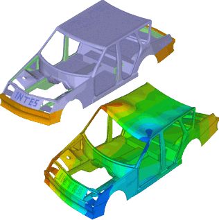
The results from a frequency response analysis are any complex primary result (displacements, velocities, or accelarations) and secondary result (e.g. stresses, strains, sound radiation power density) for all nodes at any excitation frequency. Frequently, so-called transfer functions are more important than the full fields of result quantities. Transfer functions describe the relation between the excitation points and any target point of interest (by a unit excitation) for all excitation frequencies.

In order to reduce computational effort for response analysis the user can specify the requested results in advance. In case of requested transfer functions, the response analysis can be restricted to a node set.

INTEScar

Example INTEScar under torsional loading.

Fluid-Structure Dynamics
Coupled simulation of structure and air is seen as natural extension of structural dynamics. This extension is needed, because noise in a car is a combination of structural-borne and air-borne noise. Noise at the driver's ear is important for the comfort and the acoustic quality of a car.

As a first step the interior of the car is modeled by so-called fluid elements which are classical volume elements but with a pressure degree of freedom. In order to model the coupling between structure and air physically, there are additional coupling (or interface) elements which contain both the displacement and pressure degrees of freedom and represent the physical compatibility condition between structure and air.

To facilitate the two modeling steps for fluid and coupling elements of the car interior, VisPER contains an easy-to-use wizard starting from the structural mesh and generating the fluid mesh and the coupling elements step by step in an almost automatic way. Typically, the coupling elements are compatible with structural elements of the interior surface, but the fluid elements representing the enclosed air are incompatibly meshed, because the mesh for the air is usually much coarser than for the structure. The wizard derives the appropriate element edge length from the requested frequency range.

The fluid may contribute to the damping by so-called volumetric drag which represents the absorption in a fluid volume. The coupling elements contribute to the damping by surface absorption which represents a normal impedance of the coupling surface.

Solution of coupled system After completing the fluid-structure model, the analysis steps are very similar to structural dynamics of cars as described above:
  • A coupled eigenvalue analysis is available to derive the coupled eigenfrequencies and mode shapes. The mode shapes consist of two corresponding parts, a displacement mode shape of the structure and a pressure mode shape of the fluid.
  • Excitations can now also be specified in the fluid by a pressure signal.
  • Based on coupled eigenfrequencies and mode shapes, modal frequency response analysis and modal time-history response analysis can be performed in the same way as for the sole structure.
Dynamic response of coupled system In addition to modal methods, also a direct frequency response is available for fluid-structure coupled analysis.

From the coupled response results, all results as described for structural response calculations can be obtained. In addition, the pressure field in the air and transfer functions from structural points to pressure points are available (and vice versa). Moreover, sound particle velocities (as vector field or magnitudes) can be derived from the pressure field.

In addition to enclosed air in a car, the surrounding air can also be modeled and coupled to the structure. This feature can be used to calculate noise transition through the structure (from the road or from air flow induced noise to the driver's ear).

body_acoustics
Acoustic model of a car body
with enclosed and surrounding air.
High Performance
Continuous effort is spent in improving and accelerating the speed of algorithms. In car body analysis emphasis is put on the following achievements:
  • For large models (millions of degrees of freedom) and many modes (thousands of modes), eigenvalue analysis is made much faster by MLDR (Multi-Level Dynamic Reduction). This method is available for both structural dynamics and coupled fluid-structure dynamics.
  • In frequency response analysis many different dynamic load cases (several hundreds) are often applied. So-called assembled situations are used to solve these load cases simultaneously instead of one after the other.
  • In frequency response analysis the equation solving can be made much faster (for a high number of modes and many excitation frequencies) using an iterative solver.
Optimization
Supported by VisPER and PERMAS, optimization tasks for the car body can be solved in an integrated way. So, the optimization model is part of the model description and can easily use all available references to existing model parts like node and element sets. Although all available optimization types can be used for car bodies, the most important ones are as follows:
  • Sizing: This is used to optimize element properties like shell thickness, beam cross section, spring stiffness, and damper properties.
  • Shaping: This is used to optimize geometry of parts by modifying node coordinates (also possible with incompatible meshes).
  • Bead design: This is used to position and shape beads in shell structures.

All these optimization types can be combined in one optimization project. Static and dynamic analysis can be used simultaneously for optimization tasks. The optimization modeling is fully supported by VisPER. Even post-processing of optimization results can be made with VisPER.

Optimization of transfer functions due to sizing, shaping, and bead design is of major importance in dynamic analysis. This frequency response optimization can be used with an objective transfer function (i.e. a frequency dependent limit of amplitudes).

If the objective transfer function is derived from experimental results, then the optimization process is named model updating. By this process selected model parameters are modified in order to fit the simulation transfer function to the experimental one.
sill_optim
Shape optimization of a sill
with transition to neighboured parts.
Questions? Ask us!

INTES Ingenieurgesellschaft für technische Software mbH
Management:  Rolf Fischer
Breitwiesenstr. 28
70565 Stuttgart
Germany
Commercial register:  Stuttgart HRB 10 978
VAT registration number: DE 147803245
Tel.: +49 711 78499-0
info@intes.de

Click here for more flyers.