Rotating Systems
Statics
In a quasi-static analysis, which may include contact at the hub, the centrifugal forces due to rotation are taken into account. The reference system is co-rotating or inertial (with axisymmetric rotor). The static analysis is possible below critical speed.
In a linear analysis, the centrifugal stiffness and the geometric stiffness at the given rotational speed are taken into account. In a geometrically nonlinear analysis, an update of the centrifugal forces will take place.
Dynamics
In order to get the relation between eigenfrequencies and rotational speed an automatic procedure is available which directly generates all values for a Campbell diagram.
For dynamics of rotating systems, the assumption is a linearized equation of motion with constant coefficients. A co-rotating or inertial reference system is taken. If rotating and non-rotating parts are present, the rotating part can be modelled as elastic body. The rotational speed is expected to be constant.
In the case of a coupling of rotating and non-rotating parts in a co-rotating reference system, no restrictions have to be observed for the rotating parts, but the non-rotating parts have to provide isotropic support to the rotor.
For such configuration, all direct and modal methods in time and frequency domain can be applied in the subcritical and overcritical frequency range. During response analysis the Coriolis matrix is taken into account.
In the case of dynamics in an inertial reference system, no additional restrictions have to be observed for the non-rotating parts, but the rotating parts have to be axisymmetric.
Also for such configuration, all direct and modal methods in time and frequency domain can be applied taking into account the gyroscopic matrix. Modal methods remain applicable even for the overcritical range of rotational speeds.
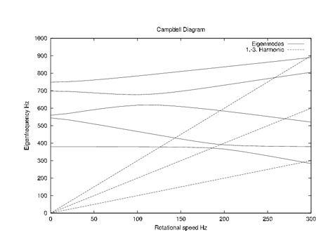
To determine the critical rotation speed a Campbell diagram can be used. In the co-rotating reference system, the Campbell diagram will show zero eigenvalue at certain rotational speed.
Rotation speed dependent stiffness and viscous damping of rotor supports can be taken into account during complex eigenvalue analysis and for the generation of a Campbell diagram. This feature can be modelled by a special element.
For dynamics modal steady-state response is of particular importance. There, the static stresses under centrifugal load are determined first. Then, with geometrical and centrifugal stiffness, the static displacements are derived. On the basis of real eigenvalue analysis, several modal frequency response analyses are performed for each harmonic. After back transformation to physical space, the results for all harmonics and the static case are superposed in the time domain.

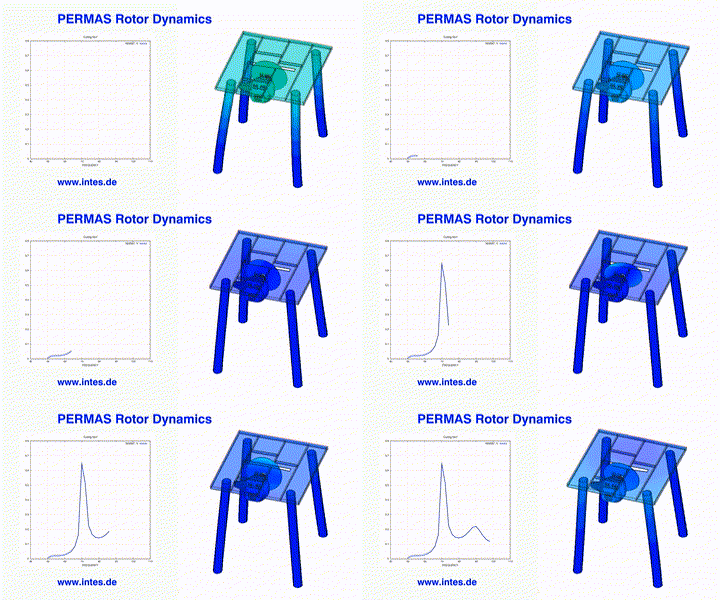
Changing vibrational behavior of a circular saw bench during run-up.

Campbell diagram for the evaluation of rotor dynamics
A flyer about this topic can be found here.
Questions? Ask us!
INTES Ingenieurgesellschaft für technische Software mbH
Management: Rolf Fischer
Breitwiesenstr. 28
70565 Stuttgart
Germany
Commercial register: Stuttgart HRB 10 978
VAT registration number: DE 147803245
Tel.: +49 711 78499-0
✉info@intes.de